FRED
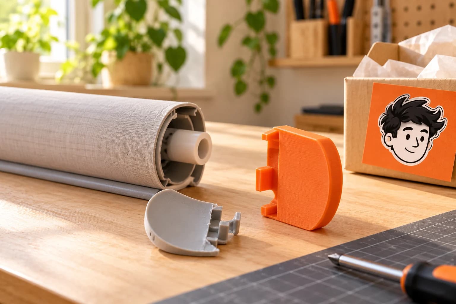
Broken blind end cover: identify the cosmetic part
A blind end cover may be decorative or may conceal an essential mechanism. Confirm its role from the manufacturer before considering a printed cosmetic replacement.
In this article
Find the exact reference
Check the blind model and parts diagram. Do not release a loaded spring, axle or suspended unit to inspect an uncertain component.
Measure the cosmetic shell
Record outer dimensions, inner clips, side and clearances. Keep fragments and compare an intact opposite cap only if its geometry actually matches.
Describe exposure
State sunlight, heat near glazing and cleaners. Material stability and clip flexibility matter; UV resistance alone does not validate an assembly.
Preserve the original safety arrangement
Do not modify cord tensioners, guards, brackets or electrical covers. Test only an appropriate non-load-bearing shell and seek professional confirmation if its clearance or function is uncertain.
Prepare suitable manufacturing with FRED
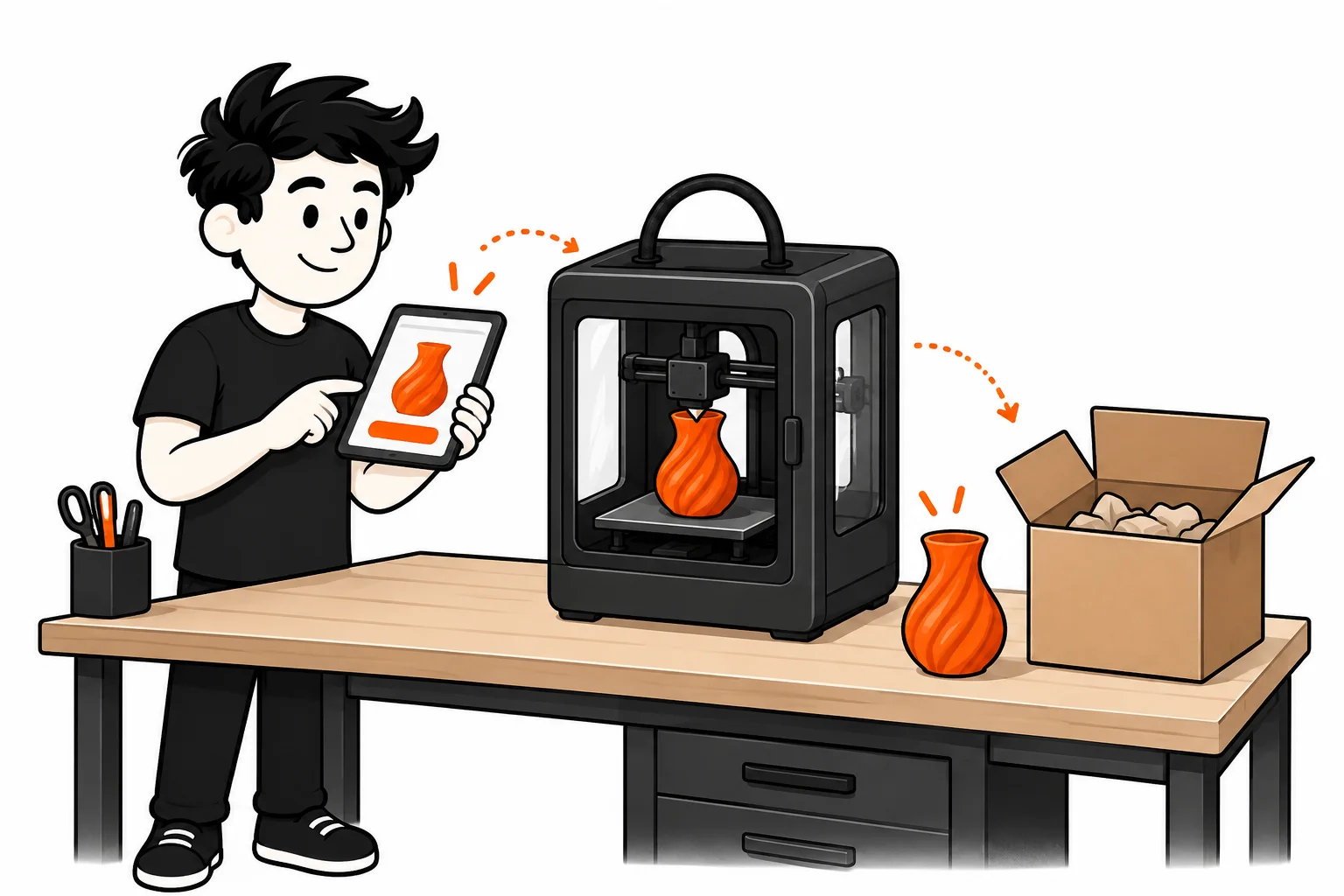
Prepare a checked STL, 3MF or OBJ for the intended use. FRED, currently in private beta, lets you configure manufacturing from that file, review the quote and follow the order with a partner manufacturer. Confirm available materials and capabilities before ordering.
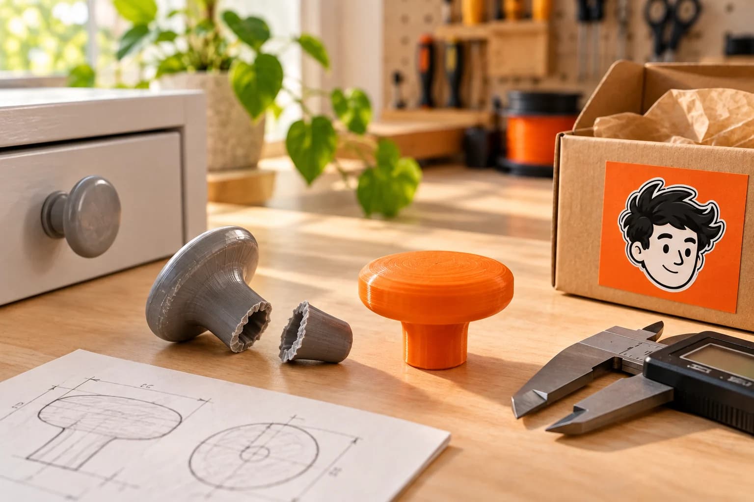
Measurement and mechanical modelling are separate from manufacturing a supplied file. Present your brief when requesting access to clarify feasibility. The cover is an AI-generated illustration, not evidence of a repair tested by FRED.
Planning a replacement part?
Gather your measurements and 3D file, then describe your project to check manufacturing options. FRED is in private beta by invitation.
Request access